How to Reduce Solar Siding Structural Load: A Guide to Light-Fram
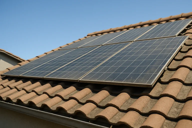
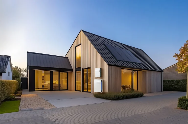
The architectural skin of a building is traditionally tasked with a finite set of responsibilities: moisture exclusion, thermal insulation, and aesthetic contribution. However, the advent of Building-Integrated Photovoltaics (BIPV) in the form of solar siding has introduced a significant mechanical variable—dead load. Unlike traditional vinyl or fiber-cement cladding, which are relatively lightweight, solar siding incorporates semi-conductors, tempered glass or high-performance polymers, and robust mounting hardware. How to Reduce Solar Siding Structural Load. This transition transforms the exterior wall from a passive barrier into a heavy, active energy asset that places unprecedented demands on the building’s structural frame.
Structural integrity in solar-integrated architecture is not merely a matter of preventing collapse; it is about managing long-term deflection and creep. A wall assembly designed for standard timber-lap siding may lack the rigidity required to support the hundreds of additional pounds introduced by a full-facade solar array. If the load is not properly distributed or mitigated, the second-order effects can include window frame warping, door misalignment, and compromised weather-sealing. Addressing these challenges requires a departure from “standard” carpentry toward a more nuanced understanding of structural engineering and materials science.
To successfully implement these systems, one must look beyond the electrical yield and focus on the mechanical marriage between the solar modules and the sheathing. The goal is to achieve energy sovereignty without sacrificing the longevity of the building envelope. This necessitates a strategic approach to material selection, mounting geometry, and load-path optimization. By analyzing the intersection of gravity and generation, we can establish a framework for high-performance cladding that remains structurally viable for the thirty-year lifespan of the photovoltaic cells.
Understanding “How to Reduce Solar Siding Structural Load”
When architects and engineers ask how to reduce solar siding structural load, they are navigating a multi-dimensional optimization problem. It is an inquiry that spans material density, fastening frequency, and the aerodynamic interaction between the wind and the facade. A primary oversimplification in this field is the belief that “lighter is always better.” While reducing mass is a core objective, it must be balanced against the rigidity required to protect fragile silicon cells from micro-cracking during wind-induced vibrations.
A multi-perspective explanation reveals that load reduction is achieved through three primary vectors: substrate optimization, module composition, and shear-force distribution. Substrate optimization involves utilizing high-strength, low-weight sub-frames, such as aircraft-grade aluminum or carbon-fiber reinforced polymers, to replace heavy steel rails. Module composition focuses on the transition from traditional “glass-glass” modules to “glass-backsheet” or even “polymer-backsheet” iterations, which can reduce the weight of the cladding by up to 40%.
The risk of oversimplification lies in ignoring the “dynamic load.” A solar siding panel does not just sit on a wall; it acts as a sail. Therefore, reducing the static weight (dead load) is only half the battle. One must also consider how to reduce the leverage that the wind exerts on the fasteners. This is achieved through low-profile mounting systems that minimize the air gap between the panel and the wall, effectively reducing the “moment arm” that could otherwise pull fasteners out of the studs.
Deep Contextual Background
The evolution of building skins has moved from heavy masonry and thick timber toward increasingly thin, lightweight membranes. Solar siding represents a counter-trend to this “thinning” of the building envelope. In the early 2000s, BIPV was largely confined to heavy, custom-engineered glass curtain walls for commercial skyscrapers. These structures were designed from the ground up to handle massive cantilevered loads.
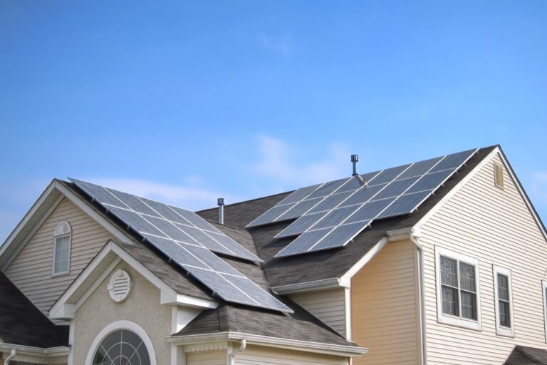
As the technology migrated to the residential sector, it encountered the “light-frame” timber construction prevalent in North America and parts of Europe. This transition created a systemic mismatch. Residential studs (typically 2×4 or 2×6) were never intended to carry the weight of glass-clad facades. The industry’s initial response was to reinforce the interior of the walls, but this was prohibitively expensive for retrofits. This friction catalyzed the current era of “mass-optimization,” where the focus shifted from reinforcing the house to lightening the solar asset. The systemic evolution is now moving toward “Thin-Film” CIGS (Copper Indium Gallium Selenide) and Perovskite technologies, which can be printed onto flexible, lightweight substrates, potentially eliminating the structural load problem entirely.
Conceptual Frameworks and Mental Models
To analyze the structural impact of solar siding, we can use the following mental models:
-
The Lever and Fulcrum Model: View every solar panel as a lever and the fastener as the fulcrum. The farther the panel sits from the wall (the “stand-off” distance), the more force is exerted on the fastener. Reducing the structural load is as much about decreasing this distance as it is about decreasing weight.
-
The Distributed Load Framework: Instead of concentrating weight on a few heavy brackets, the goal is to “atomize” the load across the entire surface of the wall. By using continuous rail systems or adhesive-integrated bonding, the stress on any single point in the timber frame is minimized.
-
The “Sacrificial” Substrate: In some advanced designs, a secondary, lightweight skin is attached to the building first. This skin handles the structural distribution of the solar panels, shielding the primary air-and-water barrier from the mechanical stress of the heavy modules.
Key Categories of Lightweight Solar Integration
Reducing load requires a selection of specific hardware and material architectures.
| Category | Description | Weight Reduction % | Primary Trade-off |
| Thin-Film CIGS | Flexible, non-glass modules. | 60–80% | Lower efficiency per sq. ft. |
| Hollow-Core Rails | Extruded aluminum sub-frames. | 15–25% | Higher material cost. |
| Adhesive Bonding | Structural tapes/glues vs. bolts. | 10–15% | Permanent; harder to repair. |
| Composite Frames | Carbon/Polymer panel frames. | 20–30% | UV degradation concerns. |
| Glass-Backsheet | Single layer of glass + polymer. | 30–40% | Reduced rear-side protection. |
Realistic Decision Logic
The choice of category depends on the age and condition of the building. For a 1920s-era home with nominal 2×4 framing, Thin-Film CIGS is often the only viable path to avoid structural failure. In new construction, where the frame can be engineered for “high-capacity” loads, the choice usually shifts toward Glass-Backsheet modules for their superior longevity and higher ROI, provided the sub-frame is optimized for weight.
Detailed Real-World Scenarios How to Reduce Solar Siding Structural Load
Scenario 1: The Historical Retrofit
A Victorian-era home requires energy upgrades, but the balloon-frame structure is sensitive to weight. The solution involves a “Hybrid Load Path.” Instead of mounting the solar siding directly to the old studs, a lightweight aluminum “hat-channel” grid is installed to bridge across multiple studs, distributing the load horizontally. This prevents the “racking” of the delicate window openings.
Scenario 2: High-Wind Coastal Implementation
On a coastal property, wind-uplift is more dangerous than gravity. Here, the load reduction strategy focuses on “aerodynamic profiling.” The solar panels are integrated with a flush-mount system that leaves no edge for the wind to catch. The second-order effect is a reduction in the “vibration-load” that would otherwise loosen fasteners over time.
Scenario 3: The Multi-Story Commercial Facade
In a five-story office building, the “accumulated load” of five levels of solar panels becomes a factor. The design employs “Load-Shifting Brackets” that transfer the weight of the panels directly to the floor slabs rather than the exterior wall studs. The failure mode avoided here is the “buckling” of the vertical studs under the compounded weight of the facade.
Planning, Cost, and Resource Dynamics
The financial planning for load-optimized solar siding involves a “cost-shifting” dynamic. While lighter materials are more expensive, they often eliminate the need for expensive structural reinforcements.
| Item | Estimated Range (USD) | Variability Factor |
| Thin-Film Modules | $25 – $45 per sq. ft. | Efficiency rating; brand. |
| Aluminum Rail System | $5 – $12 per sq. ft. | Complexity of the grid. |
| Structural Engineer | $1,500 – $4,000 | Site location; permit requirements. |
| High-Shear Fasteners | $0.50 – $2.00 each | Material (Stainless vs. Coated). |
Opportunity Cost: Choosing heavy, cheap glass modules today might save $5,000 in hardware but trigger a $15,000 interior wall reinforcement project. Calculating the “Total System Weight” per square foot is the primary resource metric during the planning phase.
Tools, Strategies, and Support Systems
-
Laser Scanners: Used to create a 3D model of the existing wall to identify “bowing” or structural weaknesses before installation.
-
Point-Load Software: Digital simulations that show how weight moves through the studs under different wind conditions.
-
Hat-Channel Grids: A support system that provides a flat, rigid surface for solar panels while remaining lightweight.
-
Counter-Battening: A technique that creates a “ventilation cavity” behind the panels, which also helps in load distribution.
-
Structural Adhesives: High-performance VHB (Very High Bond) tapes that can replace hundreds of metal screws, reducing both weight and thermal bridging.
-
Tension Cables: In specific cantilevered designs, thin cables can “suspend” the weight of the facade from the roof-plate, taking the pressure off the walls.
Risk Landscape and Failure Modes
The primary risk in load-reduction is Fastener Fatigue. If a system is made too light by using fewer fasteners, those few points of contact undergo massive stress.
Compounding Risks:
-
Galvanic Corrosion: If aluminum rails are fastened with steel screws without a thermal break, the rail can weaken and eventually fail under the weight of the panels.
-
Thermal Creep: As panels heat up, they expand. If the mounting system doesn’t allow for this movement, the “thermal load” can bend the support rails, even if the static weight is low.
-
Moisture Retention: Lightweight systems that sit too close to the wall can trap moisture, leading to rot in the timber studs, which eventually destroys the wall’s ability to carry any load at all.
Governance, Maintenance, and Long-Term Adaptation
Long-term structural viability requires a “Governance Plan” that treats the facade as a mechanical system.
-
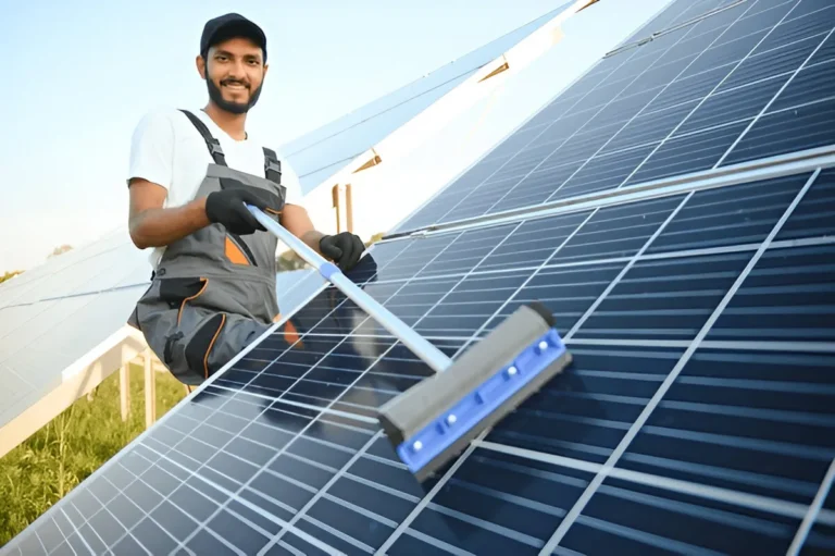
Biannual Fastener Torque Checks: Especially in the first two years, checking that the fasteners haven’t “backed out” due to thermal cycling.
-
Deflection Monitoring: Using simple reference points on the wall to check if the siding is sagging over time.
-
Adaptive Re-Skinning: Designing the system so that as panels become lighter and more efficient in ten years, they can be swapped out without replacing the entire sub-frame.
Measurement, Tracking, and Evaluation
-
Leading Indicators: Fastener pull-out resistance tests (performed during install); rail deflection measurements under full sun.
-
Lagging Indicators: Interior drywall cracking; window/door sticking; moisture levels in the sheathing.
-
Qualitative Signals: “Creaking” sounds during high winds; visual “waving” in the line of the siding when viewed from the side.
Documentation Examples
-
Load-Path Map: A diagram showing exactly how the weight of the solar panels reaches the foundation.
-
Fastener Schedule: A log of every screw used, its material, and its torque setting.
-
Shear Analysis Report: A document from a structural engineer verifying that the wall can handle the wind-plus-gravity load.
Common Misconceptions and Oversimplifications
-
“OSB can handle the weight”: Oriented Strand Board (OSB) is not a structural mounting point. Fasteners must hit the studs to manage the load.
-
“Glue is enough”: While adhesives are great for load distribution, they should almost always be paired with mechanical “safety fasteners” to prevent catastrophic failure if the glue fails.
-
“Standard siding is heavy too”: Fiber-cement is heavy, but it is not “cantilevered.” Solar panels often sit 1–2 inches off the wall, which effectively triples their perceived weight on the fasteners.
-
“Permits aren’t needed for siding”: Any time you add significant weight to a structure, a permit and an engineer’s sign-off are typically required by law.
Ethical and Practical Considerations
There is a practical “Duty of Care” in solar siding installation. Installing a heavy system on a building with a compromised foundation is unethical. Practically, we must also consider the “Embodied Carbon” of the load-reduction materials. If we use high-energy aluminum and carbon fiber to save weight, we must ensure the energy yield of the solar cells justifies that initial carbon “debt.” Furthermore, we must consider the “Deconstruction Factor”—can the system be easily removed without destroying the building’s primary structure?
Synthesis and Future Adaptability
The ultimate goal of learning how to reduce solar siding structural load is to make energy generation an effortless part of architectural design. The future of this field lies in “Material Synthesis,” where the structural substrate and the photovoltaic cell are manufactured as a single, lightweight unit.
As we move toward “Net Zero” building codes, the ability to manage the physics of the facade will become as important as the ability to manage the electronics. A successful project is one where the gravity of the system is mastered so completely that the house remains as stable and resilient as the day it was built, yet functions as a high-output power plant for decades.