Common Solar Siding Wiring Mistakes: A Guide to Resilient Facade
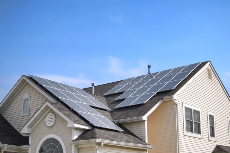
The architectural transition toward Building-Integrated Photovoltaics (BIPV) represents a shift from “adding” energy components to “embedding” them. While rooftop solar has reached a level of standardized installation, solar siding introduces an entirely different set of environmental and mechanical stressors. In a rooftop scenario, wiring is largely protected by the panels themselves or tucked into conduits above the roof plane. Common Solar Siding Wiring Mistakes. With solar siding, the wiring exists within the building envelope—sandwiched between the exterior aesthetic layer and the structural sheathing. This proximity to the living space and the vertical orientation of the array complicates heat dissipation and moisture management.
The failure of a solar siding system is rarely due to a defect in the photovoltaic cells themselves; rather, it is almost always a failure of the interconnectivity. Because these systems are vertical, they are subject to different thermal expansion coefficients than horizontal arrays. The wiring must be able to “breathe” and move alongside the building’s natural settling and seasonal shifts. When these dynamics are ignored, the result is more than just a drop in efficiency; it can lead to arcing, localized hotspots, and compromised structural integrity.
To master the installation of these systems is to understand the invisible life of electrons moving behind a decorative facade. It requires a multidisciplinary approach that combines the precision of a master electrician with the moisture-mitigation expertise of a rain-screen specialist. This exploration moves beyond surface-level checklists to analyze the systemic failures that occur when the electrical and architectural worlds collide without proper synchronization.
Understanding “Common Solar Siding Wiring Mistakes”
Identifying common solar siding wiring mistakes requires a fundamental shift in perspective. Most installers approach solar as a DC-current problem, but in the context of siding, it is primarily a “confinement” problem. A vertical array often involves hundreds of small connections tucked into narrow channels. A primary misunderstanding is the belief that standard MC4 connectors and PV wire used on roofs are universally appropriate for siding. In reality, the limited airflow behind siding panels means that wiring often operates at temperatures 20–30 degrees higher than ambient air, leading to accelerated insulation degradation if the gauge or temperature rating is miscalculated.
Oversimplification in this field often leads to the “daisy-chain” trap. While stringing panels together in series is efficient on a roof, doing so behind siding without adequate bypass diodes or specialized junction boxes creates a scenario where a single shaded panel (perhaps from a nearby tree or an architectural overhang) bottlenecks the entire facade. Furthermore, many mistakes stem from a lack of “service loop” planning. Because solar siding is a permanent cladding material, wiring that is pulled too taut will eventually snap or disconnect due to the thermal expansion of the aluminum or composite frames.
The risk of these mistakes is compounded by the “invisible” nature of the fault. Unlike a leaky pipe, a loose connection or a pinched wire behind a panel may not trigger an immediate system shutdown. Instead, it creates high-resistance points that slowly bleed energy as heat, potentially charring the building’s house-wrap or sheathing long before a thermal camera or a monitoring app detects a significant anomaly.
Deep Contextual Background
The lineage of BIPV wiring can be traced back to the first glass-curtain walls of the late 20th century, where solar cells were integrated into commercial skyscrapers. In those high-budget environments, wiring was handled through custom-engineered mullions. As the technology moved to the residential sector, the challenge became how to provide that same level of electrical safety within the budget and physical constraints of a 4-inch or 6-inch siding plank.
Early residential solar siding often used “ribbon” connectors—thin, flat conductors designed to minimize the profile of the siding. However, these were notoriously difficult to terminate and prone to cracking under vibration. The industry has since moved toward specialized micro-junction boxes integrated into the back of the cladding. This evolution has moved the complexity from the field to the factory, but it has introduced a new systemic risk: the “black box” installation. If an installer does not understand the internal circuitry of a pre-wired panel, they are more likely to create mismatched string voltages or exceed the maximum series fuse rating of the inverter.
Conceptual Frameworks and Mental Models
To analyze the wiring of a solar facade, one should utilize these mental models:
-
The Rain-Screen Analogy: View the wiring channel not as a dry conduit, but as a “wet” environment. Just as a rain-screen siding expects water to get behind it, the wiring must be rated for “wet” or “damp” locations (typically USE-2 or RHW-2) to survive the condensation that naturally forms behind the facade.
-
The Thermal Expansion Accordion: Imagine the entire siding system as a musical instrument that expands and contracts. Every wire must have enough “slack” (a service loop) to act like an accordion, absorbing the 1/8-inch of movement that occurs across a 10-foot run during a 50-degree temperature swing.
-
The Bottleneck Theory: In a series-wired siding array, the system is only as strong as the wire behind the lowest-performing panel. This model dictates that wiring paths must be designed to minimize the impact of “architectural shading” (shading caused by the house’s own features).
Key Categories and Variations
The method of interconnecting solar siding determines the system’s long-term resilience and its susceptibility to common solar siding wiring mistakes.
| Category | Description | Primary Benefit | Significant Trade-off |
| Series Stringing | Standard daisy-chaining of panels. | Lower wire cost; higher voltage. | High sensitivity to shade; risk of high-voltage DC arcing. |
| Micro-Inverter Per Panel | AC conversion at each siding unit. | Maximum shade tolerance; lower DC risk. | High hardware cost; more points of electronic failure behind cladding. |
| Parallel Branching | Low-voltage DC combined at the bus. | Safety; lower voltage stress on insulation. | High current (Amps) requires very thick, expensive wiring. |
| DC Optimizers | Module-level power electronics (MLPE). | Balances mismatched outputs; good monitoring. | Requires space behind siding for the optimizer box. |
Realistic Decision Logic
A south-facing wall with zero obstructions is an ideal candidate for series stringing, as the simplicity reduces the number of connectors—the primary failure point. However, a multi-story facade with gables and overhangs should almost exclusively utilize DC optimizers or micro-inverters. The initial cost increase is offset by the elimination of “mismatch losses” that would otherwise plague a series-wired string.
Detailed Real-World Scenarios Common Solar Siding Wiring Mistakes
The Pinched Conductor
During the installation of a fiber-cement solar siding project, a carpenter accidentally pins a PV wire between the panel and a metal starter strip. Over six months, the vibration of the wind causes the metal to saw through the insulation. The second-order effect is a “ground fault” that shuts down the inverter every time it rains. This scenario highlights the need for dedicated “wire chases” that keep conductors away from fastening points.
The “Sun-Baked” Connector
An installer leaves several MC4 connectors resting against the dark, heat-absorbent back-sheet of the solar siding. In the peak of summer, temperatures behind the panel reach 175°F (80°C). The plastic housings of the connectors undergo thermal cycling and eventually crack, allowing moisture to enter. This is a classic example of failing to manage the “thermal microclimate” behind the facade.
The Mismatched String Length
A facade is split into two sections: one with 10 panels and one with 12, both wired into the same MPPT (Maximum Power Point Tracking) input. Because the voltages are unequal, the inverter struggles to find the “sweet spot,” resulting in a 15% energy loss. This planning error is often discovered only after the siding is fully nailed in, making the correction prohibitively expensive.
Planning, Cost, and Resource Dynamics
The economic profile of wiring for solar siding is defined by “Labor-Intensity.” While the materials (wire and connectors) may only account for 5–8% of the total project budget, the labor to route them safely through the building envelope can account for 20%.
| Expense Item | Estimated Range (USD) | Variability Factors |
| PV Wire (10/12 AWG) | $0.80 – $2.50 per foot | Copper price; insulation rating (XLPE vs PVC) |
| Connectors (MC4/Specialty) | $5 – $15 per pair | UV rating; integrated locking mechanisms |
| Wire Management (Clips/Chases) | $200 – $800 per project | Use of stainless steel vs. plastic; complexity |
| Electrical Commissioning | $500 – $1,500 | Requirement for insulation resistance (megger) testing |
Opportunity Cost: Attempting to save $500 on cheaper, thinner-gauge wire often results in a 2% voltage drop across a 100-foot run. Over a 25-year lifespan, that 2% loss can equate to thousands of dollars in ungenerated revenue—far exceeding the initial “savings.”
Tools, Strategies, and Support Systems
To mitigate common solar siding wiring mistakes, installers must utilize specialized diagnostic and protective tools:
-
Thermal Imaging Cameras: Used during the first full-sun day post-installation to identify “hot” connectors or pinched wires before they cause damage.
-
Insulation Resistance Testers (Meggers): Essential for verifying that no wire insulation was nicked during the siding nailing process.
-
Strain Relief Clips: Stainless steel clips that prevent the weight of the wire from pulling on the junction box terminations.
-
Bypass Diodes: Integrated into the siding panels to allow current to “flow around” shaded or damaged cells.
-
Corrosion-Inhibiting Greases: Applied to connectors in coastal environments to prevent the “creeping” salt-spray from oxidizing contacts.
-
Cable Management Systems (CMS): Dedicated plastic or metal channels that create a “safe zone” for wiring behind the cladding.
Risk Landscape: Taxonomy of Electrical Failures
The risk profile of solar siding is tiered by the severity of the consequence:
-
Type I: Efficiency Degradation: Caused by poor termination or undersized wiring. The system works, but “leaks” energy as heat.
-
Type II: Premature Component Death: Caused by heat-trapping behind the panel. This leads to the “cooking” of diodes and capacitors within micro-inverters or optimizers.
-
Type III: Fire and Arcing: The most severe risk. High-voltage DC arcs are self-sustaining and can reach temperatures of several thousand degrees. If a wire is nicked and the “arc-fault” detection on the inverter fails, the result is an active ignition source behind the siding.
Governance, Maintenance, and Long-Term Adaptation
A solar siding system is a “live” infrastructure that requires a governance strategy to manage its three-decade lifespan.
The Multi-Year Maintenance Cycle
-
Quarterly: Review the digital monitoring platform for “clipping” or sudden drops in output that indicate a loose connection.
-
Annually: Perform a visual inspection of the “weep holes” at the bottom of the siding to ensure no wires have fallen and are blocking drainage.
-
Every 5 Years: Conduct a drone-based thermal scan of the facade to identify any internal wiring resistance issues that aren’t yet causing a system fault.
Long-term adaptation involves “Inverter Upcycling.” As battery-ready hybrid inverters become the standard, the wiring at the “combiner box” level may need to be reconfigured to handle the higher-voltage requirements of modern storage integration.
Measurement and Tracking Qualitative Signals
Quantitative data (kWh) tells only part of the story. Qualitative signals are the early warning system for wiring health.
-
Audible Noise: A faint “buzzing” or “crackling” behind the siding during peak sun is a definitive signal of an active arc-fault.
-
RF Interference: If the home’s WiFi or radio reception degrades significantly when the sun comes out, it often suggests poorly shielded DC wiring or a failing inverter capacitor.
-
“Ghost” Faults: Inverters that shut down only during humid or rainy mornings often have “micro-cracks” in the wire insulation that are only bridged by moisture.
Documentation Examples
-
As-Built Wiring Map: A photographic record of all wire runs before the final siding panels are snapped into place.
-
String Voltage Log: A record of the Voc (Open Circuit Voltage) for each string taken during commissioning to serve as a baseline for future troubleshooting.
-
Thermal Baseline Report: A set of infrared photos taken in Year 1 to compare against in Year 10.
Common Misconceptions and Oversimplifications
-
“Any siding contractor can do the wiring”: Wiring solar siding is a specialized trade. A general contractor may not understand the “minimum bend radius” required for PV wire, leading to internal conductor fatigue.
-
“Conduit isn’t needed behind siding”: While technically true in some jurisdictions, using a flexible conduit or protective “sleeve” in high-traffic or high-vibration areas is a best practice that prevents long-term insulation failure.
-
“Standard wire nuts are fine”: Never use standard twist-on wire nuts for DC solar applications. Only use specialized, weather-rated locking connectors (like MC4) or terminal blocks designed for high-vibration environments.
-
“The siding is the ground”: Even if the siding frames are metal, they cannot serve as the electrical “grounding conductor.” A dedicated green copper wire must be bonded to every panel frame to ensure safety.
Ethical and Practical Considerations
There is an ethical imperative for installers to prioritize “Disconnect Accessibility.” In the event of a structure fire, firefighters need a clear, labeled, and accessible way to de-energize the entire facade. Burying the disconnect switch behind architectural features or failing to label the “DC Source” lines creates a life-safety hazard.
Synthesis and Future Adaptability
The mastery of solar siding lies in the tension between aesthetics and physics. The wiring is the most vulnerable part of the system because it is where the “ideal” world of the electrical diagram meets the “messy” world of construction sites and weather. By anticipating common solar siding wiring mistakes—from thermal expansion to moisture ingress—the architect and the installer can move from a “install and forget” mindset to a “resilient design” framework.
As we move toward a future of “Smart Facades” where every panel might have its own sensor, the wiring infrastructure we build today must be capable of handling not just power, but data. The homes that thrive in the coming decades will be those that treated their exterior walls not as static barriers, but as high-performance, interconnected energy assets.