The Definitive Guide to Bifacial Solar Cells: Technology, ROI, and Implementation
The global transition toward renewable energy has moved beyond the initial novelty of capturing sunlight. We have entered an era defined by marginal gains and structural optimization, where the efficiency of a square meter of silicon is no longer the only variable that matters. Bifacial Solar Cells. In this high-stakes landscape, the emergence of bifacial technology represents a fundamental shift in how we perceive light harvesting. No longer is the solar panel a one-sided collector; it has become a volumetric harvester, capable of capturing energy from the direct sky and the reflected environment simultaneously.
The premise of this technology is deceptively simple: why ignore the light that hits the back of a cell? However, the execution of this concept introduces a layer of complexity that touches on semiconductor physics, structural engineering, and the granular science of albedo. To understand the current state of “Bifacial Solar Cells” is to understand a convergence of manufacturing breakthroughs that have finally made dual-sided generation economically viable on a massive scale.
This article serves as a definitive exploration of the bifacial landscape. It moves past the marketing brochures to examine the technical constraints, the environmental variables that dictate performance, and the long-term operational realities of deploying these systems. As the industry shifts away from traditional monofacial P-type modules toward more sophisticated N-type architectures like TOPCon and HJT, the bifacial factor has transitioned from a premium niche to the standard expectation for utility-scale development.
Understanding “Bifacial Solar Cells”
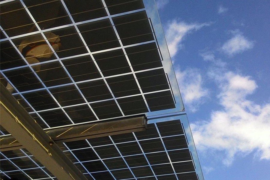
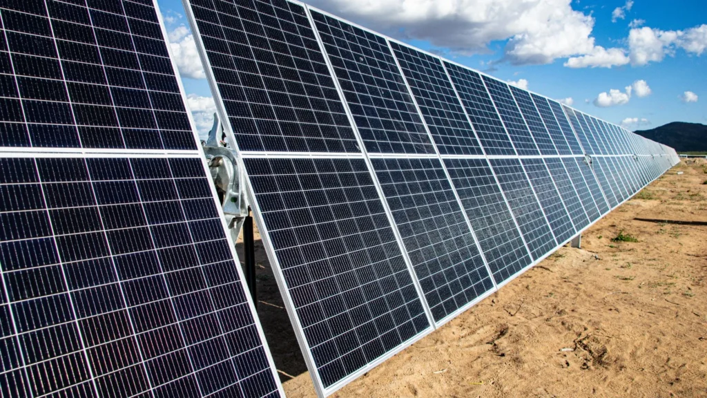
At its most fundamental level, a bifacial cell is a photovoltaic device designed to allow light to enter from both the front and rear surfaces. While a standard monofacial cell uses an opaque backsheet—often made of white tedlar—to protect the cell and reflect internal light back through the silicon, bifacial designs replace this with transparent glass or clear backsheets. This allows the cell to capture “albedo” light: the solar radiation reflected from the ground, nearby structures, or even diffuse light scattered by the atmosphere.
A common misunderstanding is the assumption that a bifacial module is simply two solar cells glued back-to-back. In reality, it is a single cell where the rear electrical contacts are redesigned to be thin or grid-like, minimizing shading on the backside. The physics of this requires a high degree of “bifaciality factor”—a ratio comparing the efficiency of the rear side to the front side. Modern high-end cells typically achieve bifaciality factors between 70% and 95%.
Oversimplification often leads developers to believe that bifaciality provides a flat percentage “boost” regardless of the environment. This is a fallacy. The energy gain is highly non-linear and sensitive to the “view factor” (the angle at which the rear of the panel sees the ground) and the surface reflectivity. A bifacial module installed on dark asphalt may see a negligible 2% gain, while the same module installed over white gravel or snow could see gains exceeding 25%.
Deep Contextual Background
The concept of bifaciality is not new; it dates back to the 1960s and 70s, primarily as a curiosity in laboratory settings or for specialized space applications where every gram of weight and every milliwatt of power were critical. For decades, however, the cost of silicon and the complexity of manufacturing transparent rear contacts made the technology prohibitive for terrestrial use.
The shift began in the mid-2010s. As the cost of crystalline silicon plummeted due to massive scale in China, the industry’s focus shifted from “cost per watt” to “Levelized Cost of Energy” (LCOE). Engineers realized that once the fixed costs of land, permitting, and labor were paid, adding a few cents to the module cost to unlock 10% more energy from the backside was a winning mathematical play.
The systemic evolution was also driven by the move toward “Passivated Emitter and Rear Cell” (PERC) technology. As PERC became the industry standard, the transition to bifacial PERC was relatively simple from a manufacturing standpoint. This was followed by the rise of N-type cells, which are inherently more conducive to bifacial designs because they suffer less from Light-Induced Degradation (LID) and offer higher efficiency ceilings on both sides of the wafer.
Conceptual Frameworks and Mental Models
To master the application of bifacial technology, one must move beyond simple electrical diagrams and adopt specific mental models:
-
The Albedo Funnel: Visualize the ground beneath the array not as a static surface, but as a secondary light source. The quality of this source is determined by its texture and color. This framework forces a shift in focus from the panel to the “ground-to-module” relationship.
-
The Shadow-Light Interplay: In monofacial systems, the shadow cast by the panel is irrelevant to its own production. In bifacial systems, the shadow is a “resource deficit.” If the panel is too low to the ground, it shades the very area it needs to reflect light from.
-
The Bifaciality Ceiling: Every cell architecture has a theoretical limit to how much light the rear can process compared to the front. Understanding this limit helps in managing expectations—a PERC cell will never behave like a HJT (Heterojunction) cell in its rear-side response.
Key Categories and Variations
Not all “Bifacial Solar Cells” are created equal. The market is currently segmented by the underlying semiconductor architecture and the module’s physical construction.
| Technology Type | Typical Bifaciality Factor | Key Advantage | Major Trade-off |
| p-PERC | 65% – 75% | Lowest cost, mature supply chain | Lower rear efficiency, higher degradation |
| TOPCon (N-Type) | 80% – 85% | High efficiency, low LID | More complex manufacturing |
| HJT (Heterojunction) | 90% – 95% | Highest bifaciality, low temp co-efficient | Higher initial CAPEX |
| IBC (Back Contact) | 50% – 80% | Best aesthetics, no front shading | Extremely complex rear-side geometry |
Realistic Decision Logic
When choosing between these categories, the decision is rarely based on peak efficiency alone. In a desert environment with high UV and high temperatures, the low temperature coefficient of HJT may justify the cost. In a standard utility-scale project on grassy terrain, TOPCon has become the “sweet spot” for balancing cost and performance.
Detailed Real-World Scenarios Bifacial Solar Cells
Scenario 1: The High-Albedo Arctic Deployment
In regions with consistent snow cover, bifacial modules can overperform their nameplate capacity by significant margins. However, the failure mode here is “backside occlusion” caused by blowing snow sticking to the rear glass. The second-order effect is that the extra energy produced can actually warm the module slightly, helping to shed snow faster than monofacial counterparts.
Scenario 2: Vertical Agri-PV
Installing modules vertically, facing East-West, allows for farming machinery to pass between rows. This setup relies entirely on bifaciality. The production curve shifts from a single midday peak to two peaks (morning and evening). The constraint here is wind loading; vertical panels act as sails, requiring much more robust racking.
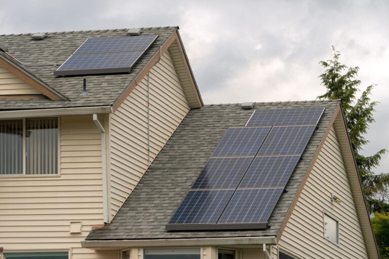
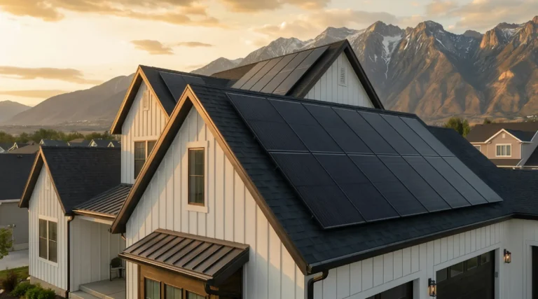
Scenario 3: Flat Roof Commercial Arrays
On a white TPO (thermoplastic polyolefin) roof, bifaciality is highly effective. But a common mistake is placing the modules too close to the roof surface to “hide” them from street view. This chokes the light path to the rear, rendering the bifacial capability useless.
Planning, Cost, and Resource Dynamics
The financial model for bifacial systems must account for “Bifacial Gain”—the extra energy produced relative to a monofacial system. While the modules themselves might only cost 1-3 cents more per watt, the total system cost changes because of structural requirements.
| Cost Element | Monofacial Impact | Bifacial Impact |
| Module Cost | Baseline | +2% to +5% |
| Racking/Mounting | Standard | +5% to +10% (height/shading req) |
| BOS (Inverters) | Sized for peak front | Sized for “Clipping” risk (oversized) |
| O&M | Standard cleaning | Potential need for rear-side cleaning |
The opportunity cost of not using bifacial in a high-albedo area is often a 5-10% increase in LCOE. Conversely, the risk of “inverter clipping” is real; if a system is undersized, the extra power from the rear side is simply lost as heat because the inverter cannot process the surge.
Tools, Strategies, and Support Systems
Deploying “Bifacial Solar Cells” effectively requires specialized simulation and hardware:
-
Ray-Tracing Software: Traditional PV modeling is insufficient. Tools must use Monte Carlo ray-tracing to simulate how light bounces off the ground.
-
Albedometers: Sensors placed on-site to measure the ground reflectivity in real-time, rather than relying on satellite averages.
-
Tube-less Racking: Mounting structures designed without a center rail that would shade the rear of the cells.
-
High-Clearance Trackers: Single-axis trackers that sit 2-3 meters high to maximize the rear “view factor.”
-
String Inverters with High MPPT Current: Bifacial modules often push higher amperages that can overwhelm older central inverters.
Risk Landscape and Failure Modes
The primary risk in bifacial systems is asymmetric degradation. If the rear of the cell degrades faster than the front (due to moisture ingress through a clear backsheet), it can create electrical imbalances. Furthermore, “Potential Induced Degradation” (PID) can be more aggressive in bifacial modules because there are more conductive paths on both sides of the laminate.
Compounding this is the “Shadow Mismatch” risk. If a mounting bracket casts a sharp shadow on the rear side while the front is in full sun, it can create localized hotspots. Over 20 years, these hotspots can lead to micro-cracking or even catastrophic backsheet failure.
Governance, Maintenance, and Long-Term Adaptation
Maintaining a bifacial site requires a different checklist than traditional solar farms:
-
Vegetation Management: In monofacial sites, weeds are just a fire hazard. In bifacial sites, tall weeds directly “kill” the rear-side production by shading the ground.
-
Ground Surface Integrity: If the site was designed for a 20% albedo based on crushed stone, and that stone becomes covered in dust or silt over five years, the project’s ROI will deviate from the pro forma.
-
Rear-Glass Inspection: Bifacial modules are often “glass-glass,” making them heavier and more prone to edge-clamping stress. Annual thermal imaging from the rear of the array is a necessary adaptation.
Measurement, Tracking, and Evaluation
How do we know if the bifaciality is actually working? Leading indicators include real-time rear-side irradiance measurements compared to total string output. A lagging indicator is the specific yield (kWh/kWp) compared to a monofacial “control” string on the same site.
Documentation Examples:
-
Albedo Mapping: A monthly log of ground reflectivity across different zones of the site.
-
Clipping Analysis: Reports showing how many hours the system hit the inverter limit, suggesting that the bifacial gain was “too high” for the electrical infrastructure.
-
Bifaciality Factor Decay: Tracking the ratio of front/rear performance over a 10-year period to identify premature aging.
Common Misconceptions
-
“They work in the dark”: No, they require light. They just aren’t picky about which direction it comes from.
-
“They are only for trackers”: While trackers maximize gain, fixed-tilt bifacial systems are highly effective on rooftops with high-reflectivity coatings.
-
“The back is 100% efficient”: The rear side is always less efficient than the front due to the metal gridlines required for structural integrity.
-
“Glass-glass is indestructible”: While durable, the lack of a frame in some bifacial designs makes the corners extremely vulnerable during installation.
Synthesis and Future Adaptability
The shift toward “Bifacial Solar Cells” is not a temporary trend; it is the natural conclusion of the quest for higher energy density. As we move toward 2030, the industry is looking at Perovskite-Silicon tandems. Integrating bifaciality into these tandem cells will be the next frontier, potentially pushing individual module efficiencies toward 30% or more when factoring in rear-side contributions.
The true value of bifacial technology lies in its adaptability. It forces us to stop looking at solar panels as two-dimensional objects and start seeing them as integrated components of a three-dimensional environment. Success in this field requires an honest appraisal of the site, a rigorous approach to structural shading, and an understanding that the ground is just as important as the sun.